Getting the refrigerant charge right on a mini split is not a matter of adding refrigerant until the air feels cold. On this GWIN system, the additional charge comes down to the installed line-set length, the specified charge rate, and an accurate refrigerant scale.
This project is a 4-ton, five-zone system with four high-wall units and one four-way ceiling cassette. The homeowner handled the installation work, including running the line sets and electrical. I came in as the HVAC technician to finish the commissioning: check the installation, pressure test, evacuate, perform vacuum decay tests, and weigh in the additional refrigerant.
That is the appeal of an assisted DIY installation. You can put your time into the physical installation while a local professional handles the refrigerant-side work and final checks.
Important: This is an explanation of one installation, not a substitute for the equipment’s installation manual or refrigerant-handling training. This system uses R32, an A2L refrigerant. Refrigerant work requires appropriate equipment, safety procedures, and EPA Section 608 certification where applicable. The EPA’s technician certification guidance explains the federal requirements.
What You'll Learn
- Additional mini split refrigerant is calculated from model-specific piping requirements and measured by weight.
- This installation required 11.2 ounces, or 0.70 pound, of additional R32 refrigerant.
- Pressure testing, evacuation, and decay testing come before final charging and operating checks.
- Assisted DIY combines homeowner installation work with professional refrigerant-side commissioning.
Table of Contents
- Start With Commissioning, Not the Refrigerant Cylinder
- Evacuate and Decay-Test All Five Zones
- Why I Weigh In the Charge Instead of Chasing Pressure
- Calculate the Additional Mini Split Refrigerant Charge
- Set Up the R32 Charging Equipment
- Add the Measured Charge Gradually
- Check the Wall Units and Ceiling Cassette
- Tools, Certification, and the Assisted DIY Option
- What This Homeowner Spent
Start With Commissioning, Not the Refrigerant Cylinder
Before adding refrigerant, the installation needs to be ready for it. A neat-looking installation is a great start, and this homeowner did a really nice job with the line sets and exterior line-hide covers. But the technician still needs to check the actual connections and electrical work.
For this project, the professional finishing work included:
- Checking the homeowner’s installation, including the disconnect and breaker selection.
- Pressure testing the refrigerant piping.
- Evacuating each of the five zones.
- Performing vacuum decay tests before opening the service valves.
- Calculating and weighing in the additional refrigerant.
- Starting the system and checking operation at the indoor units.
Adding the correct amount of refrigerant is only one part of commissioning. It does not replace pressure testing or proper evacuation.
Evacuate and Decay-Test All Five Zones
I used a NAVAC vacuum pump and a separate micron gauge to check evacuation. On the first completed zone, the vacuum had reached about 61 microns before isolation.
The next step was the decay test: isolate the evacuated section from the pump and monitor the micron reading. For this job, I was looking for the reading to remain below 500 microns after five minutes. The isolated reading settled around 280 microns and appeared stable, but I continued monitoring rather than immediately moving on.
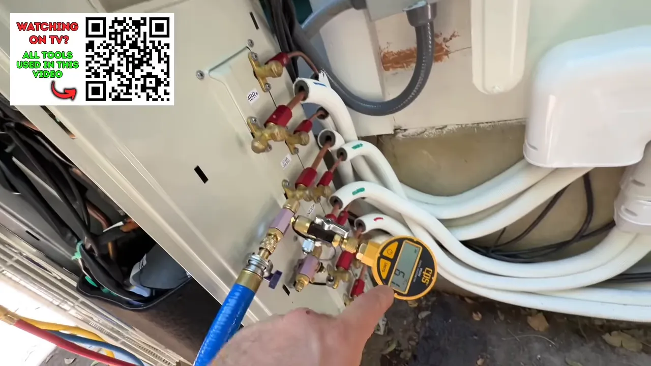
The same process needed to be completed for all five zones. Once the required checks passed, the corresponding service valves could be opened fully, following the manufacturer’s procedure.
The important distinction is between pulling a low vacuum while the pump is running and confirming that the piping holds an acceptable vacuum after isolation. Those are separate checks. The numbers here describe this installation; always use the equipment manufacturer’s evacuation and acceptance requirements for your system.
Why I Weigh In the Charge Instead of Chasing Pressure
Once the system was operating, I checked the suction-side readings across the zones. They were consistently around 120 psig at that point in operation.
Each zone has an electronic expansion valve, or EEV, that meters refrigerant to its indoor unit. The system is actively controlling refrigerant flow, so a pressure reading is an operating observation, not a stand-alone charging target.
This service arrangement provided suction-side access without a high-side connection for measuring liquid pressure. That meant I could not use a conventional subcooling measurement here. Instead, the additional charge was calculated from the line-set length and weighed in.
It is worth being precise about superheat, too. A lack of high-side access does not itself prevent a suction-side superheat measurement. The point on this installation is that the charge was established by the specified weight calculation, not by adjusting to a generic superheat or subcooling target.
Calculate the Additional Mini Split Refrigerant Charge
The final line-set measurements gave us 70 feet of additional piping length for the charge calculation. The rate used for this installation was 0.16 ounce per foot.
The math works out like this:
- Additional length: 70 feet.
- Charge rate used: 0.16 ounce per foot.
- Additional refrigerant: 70 × 0.16 = 11.2 ounces.
- Converted to pounds: 11.2 ÷ 16 = 0.70 pound.
I initially estimated 10.5 ounces, but the final measured calculation was 11.2 ounces, or 0.70 pound. That final number was the charging target.
Keep the units straight. A scale set to pounds needs a target of 0.70 lb, not 7 lb. If the scale is set to kilograms, the equivalent is approximately 0.318 kg.
Also, do not automatically apply this job’s rate to another mini split. Use your model’s instructions to determine the factory-covered piping allowance, the additional length that counts, and the applicable charge rate. Do not count both tubes separately unless the manufacturer specifically tells you to calculate it that way.
Set Up the R32 Charging Equipment
This system uses R32. The cylinder connection in this setup required a left-hand-thread adapter to a standard right-hand quarter-inch hose connection. That reverse thread is easy to overlook if you are used to conventional cylinder fittings.
Check the actual cylinder connection and use the correct adapter. Do not force a fitting because it looks close.
The charging setup consisted of a refrigerant cylinder, manifold and hoses suitable for the refrigerant, and a digital scale. The center hose connected to the cylinder, while the blue hose connected to the system’s suction service port. The red high-side hose was not being used to access the system.
Air must not be introduced through the charging hoses. Preparing the hoses and connections is part of the technician’s procedure, using appropriate methods that comply with refrigerant-handling requirements. Do not treat intentional refrigerant venting as a general DIY shortcut.
Zero the scale after positioning the cylinder
I placed the cylinder on the scale in the orientation used for charging, let the reading settle, selected pounds, and zeroed the display. Cylinder orientation and withdrawal method must follow the cylinder and equipment instructions.
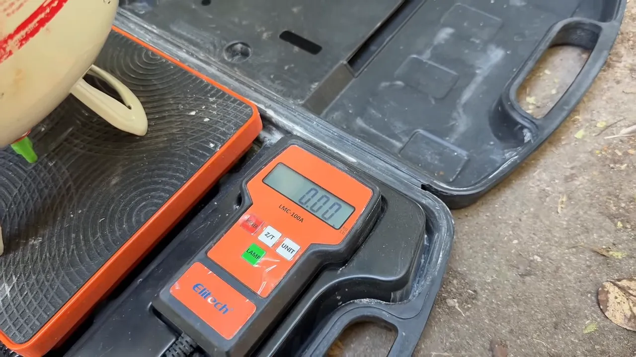
Once it is zeroed, the scale tracks the refrigerant leaving the cylinder. That is how I know the amount being added rather than trying to estimate it from pressure or charging time.
Add the Measured Charge Gradually
For this installation, the system was running in cooling mode, and I introduced the additional refrigerant through the low-side connection.
I did not open the valve wide and send the full amount in at once. I metered in a small amount, allowed the system to run for a couple of minutes, and repeated the process while monitoring the scale.
Liquid refrigerant must not be allowed to rush into the compressor. Metering, withdrawal method, and charging conditions need to follow the manufacturer’s procedure. A small total charge does not make uncontrolled charging acceptable.
The stopping point was the calculated amount: 0.70 pound added. Once that weight had been delivered, the additional line-length charge was complete. There was no reason to keep adding refrigerant just to make a pressure reading or outlet temperature look different.
Check the Wall Units and Ceiling Cassette
With the system operating, I checked the indoor units for cooling. One high-wall unit was delivering air at approximately 47°F.
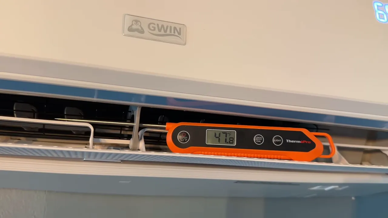
The GWIN wall head also had remote-controlled up-and-down and left-and-right airflow adjustments. That gives the homeowner a useful way to direct conditioned air into the space.
Another high-wall unit was mounted roughly 10 feet up. The hallway used a different style of indoor head: a four-way ceiling cassette. That is a nice feature of this installation, with different indoor-unit orientations serving different spaces on the same outdoor system.
At the ceiling cassette, I measured approximately 51°F, with the reading still dropping.
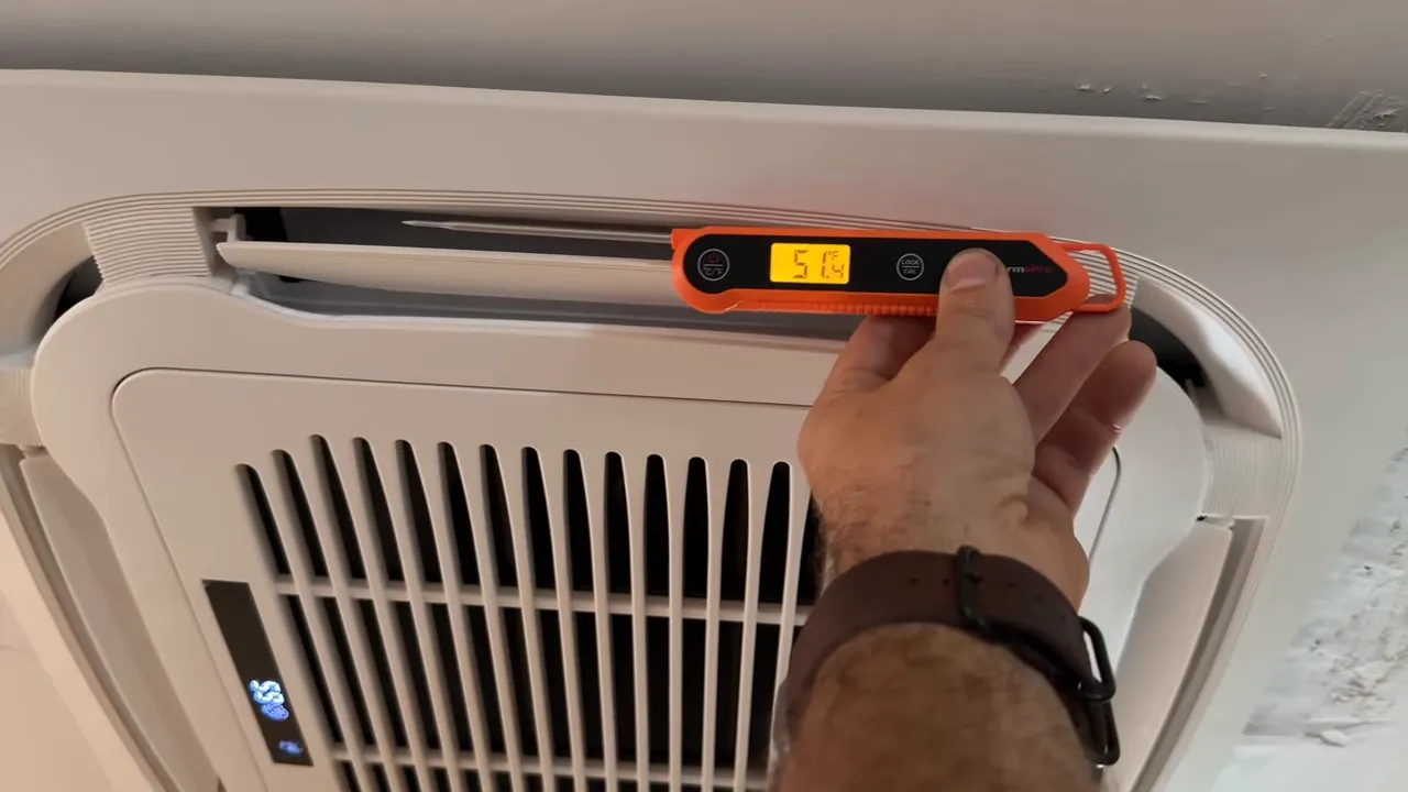
Those were encouraging operating checks, but they were not the charging method. Cold supply air supports the final operational check; it does not replace the weighed charge, pressure test, or evacuation work.
Tools, Certification, and the Assisted DIY Option
The basic measuring tools do not necessarily have to cost a fortune. At the time of this installation, I mentioned VIVOHOME gauges at around $150 and a refrigerant scale for under $100. Prices change, and compatibility with R32 and the intended work matters more than price alone.
I also mentioned purchasing refrigerant through a supplier that requires certification confirmation. Checking a box at checkout is not a substitute for actually holding the required certification and knowing how to handle the refrigerant safely.
This is where GWIN’s assisted DIY approach makes sense. The homeowner does the installation work, and a local HVAC professional comes out to handle the finishing work, including pressure testing, evacuation, and proper charging. On this project, I was that technician.
What This Homeowner Spent
The homeowner reported spending approximately $12,000 to $13,000 total on the project, including equipment and materials. He had time available and used it to install the indoor units, run the line sets, complete the electrical work, and fit the exterior line-hide covers.
For comparison, he said a next-door neighbor had spent about $30,000 on a professionally installed Mitsubishi multizone system. Those are different systems and not a like-for-like quotation comparison, but they help explain why he was so happy with the project cost. His reported total was roughly $17,000 to $18,000 below that neighboring installation.
The finished system was running nicely, with cool air indoors and heat being rejected outside. The homeowner put in a lot of work, and it showed.
The big lesson: measure the piping accurately, use the correct model-specific charge calculation, and weigh in the refrigerant. Pair that with proper installation checks, pressure testing, evacuation, and final operating checks, and you have a much stronger foundation than simply adding refrigerant until the air feels cold.
|