A full HVAC replacement can look intimidating, especially when the furnace is squeezed into a mechanical room with ductwork on both sides. But once you break the job into individual tasks, the process becomes a lot easier to understand.
On this installation, we replaced an older Tempstar system with a Goodman gas furnace, evaporator coil, and outdoor condenser. The new air conditioner uses R-32, an A2L refrigerant. Along the way, we dealt with a double return, built a custom sheet metal transition, connected the refrigerant piping, and checked both cooling and heating operation.
The big lesson? Good preparation, clean workmanship, and proper testing matter more than making the work look complicated. That does not mean skipping the qualifications or safety precautions the job requires.
What You’ll Learn
- Document wiring and connection locations before removing the old furnace, coil, and condenser.
- Keep refrigerant piping clean by preparing copper before cutting and protecting open ends.
- Plan transition seams and material allowances before cutting sheet metal panels.
- Verify the pressure test, isolated vacuum hold, cooling performance, and heating operation before finishing.
Table of Contents
- Before Starting: Know What Carries Over and What Does Not
- 1. Document the Old System Before Taking It Apart
- 2. Recover the Refrigerant and Remove the Old Equipment
- 3. Set the New Condenser and Connect the Refrigerant Lines
- 4. Fit the Furnace and Reconnect Both Returns
- 5. Set the Coil and Route the A2L Mitigation Wiring
- 6. Build the Sheet Metal Transition Without Overcomplicating It
- 7. Pressure-Test, Evacuate, and Verify the Hold
- 8. Finish the Connections and Test Both Operating Modes
- The Finished Result: Careful Work Makes the Difference
Before Starting: Know What Carries Over and What Does Not
The general replacement sequence is similar for systems using R-410A, R-32, or R-454B: remove the old equipment, fit the new equipment, complete the connections, test the refrigerant circuit, evacuate it, and commission the system.
Those refrigerants are not interchangeable, though. R-32 and R-454B are mildly flammable A2L refrigerants, and the equipment, tools, installation requirements, and mitigation controls must be appropriate for the system.
This is an educational installation walkthrough, not a substitute for the equipment manuals or qualified trade work. Refrigerant service requires the applicable EPA Section 608 certification. Electrical, gas, venting, and permit requirements also apply. Follow the manufacturer’s instructions and local code rather than treating any measurement from this particular job as a universal specification.
1. Document the Old System Before Taking It Apart
Outside, we had an aging Tempstar condenser on an existing equipment pad. Inside, the furnace and coil were tucked between other mechanical equipment and return ducts. The replacement furnace was slightly narrower, which gave us a little breathing room, but it also meant adapting the return connections.
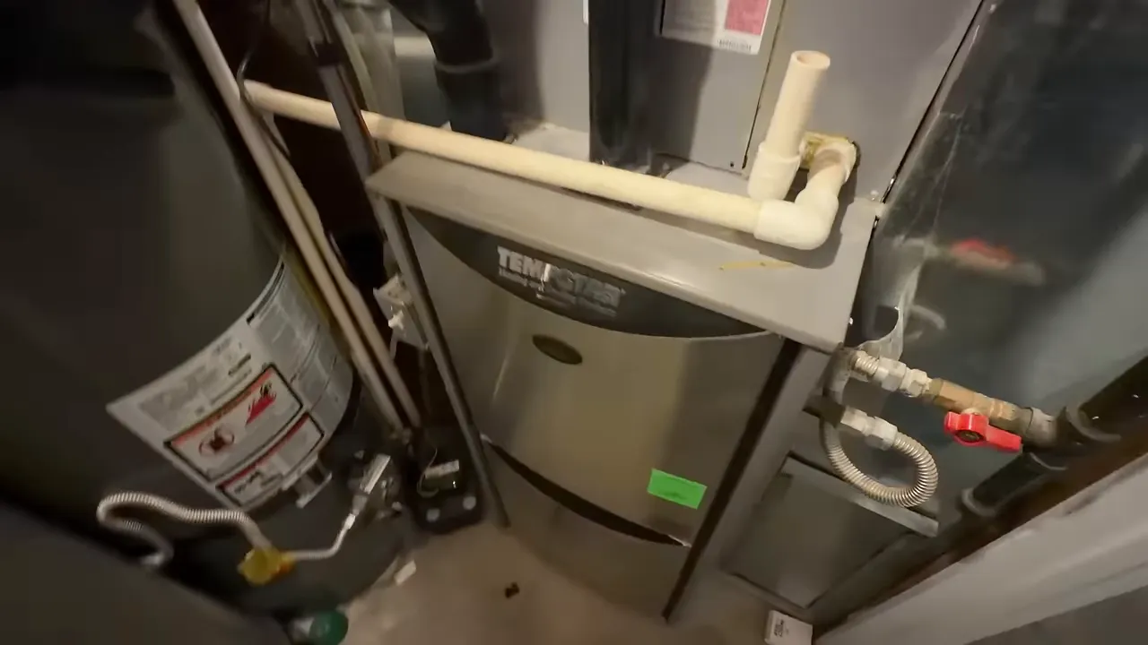
Before disconnecting anything, I like to record the wiring and connection layout. A few clear photos or a short recording can save a whole lot of head scratching later.
This system had a thermostat power extender, so there was more to document than a simple thermostat cable. Our existing connections were:
- R: Red thermostat power wire.
- C: One condenser conductor and the blue common conductor from the power extender.
- W: The gray heating conductor from the power extender.
- Y: The cooling conductor from the power extender and the other condenser conductor.
- G: The green fan conductor.
That is the wiring arrangement we found on this job, not a color guide for every furnace. Identify wires by their terminals and function, then verify the new equipment’s wiring diagram. The new A2L mitigation connections also need to be accounted for.
We also identified the gas shutoff and existing drip leg, condensate piping, vent connections, furnace electrical supply, and both return openings. The furnace breaker was not labeled, so identifying and verifying the correct circuit was part of the preparation.
2. Recover the Refrigerant and Remove the Old Equipment
We recovered the old refrigerant into a recovery cylinder before cutting the refrigerant lines. If a compressor still works, pumping refrigerant into the outdoor unit may be an option in some circumstances, but that does not eliminate the need for proper recovery when the old equipment is being retired.
Electrical supplies must be isolated and verified de-energized before disconnecting wiring. A noncontact voltage detector can help identify a circuit, but it should not be the only means of verifying that equipment is safe to work on. The gas supply also needs to be shut off before the furnace gas connection is opened.
The outdoor installation included a utility load-control device that could interrupt cooling during peak-demand periods. We removed it as part of this replacement. That is not something to copy automatically: any utility-owned or program-connected device needs to be handled with the utility’s authorization.
Make access easier before fighting the ductwork
Because the old furnace was headed for scrap, I removed its blower assembly to reach the return connections from inside the cabinet. That gave me access to the sheet metal screws on both sides without trying to squeeze tools into an impossible gap.
With the returns disconnected, refrigerant recovered, and piping and other connections safely separated, we could remove the coil, its enclosure, and the furnace.
The old transition corners were awkward to cut with hand snips. A powered cutting tool made that part of the teardown easier. Tight-space replacements often come down to finding a better way to reach or separate a connection rather than forcing the whole assembly out at once.
Clean the copper before opening it
One small habit makes a real difference: clean the outside of the copper where the connection will be made before cutting the tubing. That avoids doing abrasive cleanup right beside an open refrigerant line.
Once the lines were cut, we covered the open ends to keep dust and debris out. This matters indoors, and it matters even more outside where loose dirt and landscaping debris are right next to the work.
3. Set the New Condenser and Connect the Refrigerant Lines
With the old condenser removed, we cleaned the area, checked the existing pad, and set the new Goodman condenser level. The pad was reusable, but it still needed to be checked rather than assumed good.
We also removed the old external filter drier with the retired equipment. The new condenser on this job had its filter drier inside the outdoor cabinet, so there was no separate external drier in the finished piping. Always verify the requirements for the exact model rather than assuming every unit is arranged the same way.
Why we used Stay-Brite 8
For the copper joints on this installation, we used Stay-Brite 8, a silver-bearing solder suitable for certain refrigeration applications. The practical attraction is its lower working temperature: it can be applied with a suitable propane or MAP-Pro torch rather than an oxy-acetylene brazing setup.
Lower-temperature soldering reduces the internal copper oxidation associated with high-temperature brazing. The issue is copper oxide scale, not acid forming simply from heating the tube. Conventional refrigeration brazing generally calls for a nitrogen purge to limit that scale.
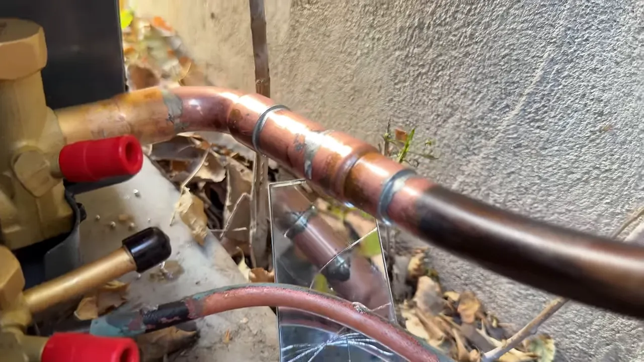
I have had good results with Stay-Brite 8 and have not personally had a leak in the joints I have made with it. We also recently removed an older installation with soldered connections that were still holding refrigerant after decades of service.
That is my experience, not blanket approval for every application. Use only the joining method, alloy, and flux permitted by the equipment manufacturer and applicable code. A quoted tensile-strength figure, such as the roughly 10,000 psi figure discussed for this solder, is not the working-pressure rating of an installed joint.
Flux control matters, too. I use a minimal amount rather than loading up the fitting, and I inspect the full circumference of the finished joint with a mirror. My experience without contamination problems is not a reason to allow flux inside the tubing.
With A2L equipment, any hot work also requires the manufacturer’s refrigerant isolation, ventilation, and ignition-control precautions. A lower-temperature torch is still an ignition source.
4. Fit the Furnace and Reconnect Both Returns
We temporarily slid the new furnace into position before cutting its return openings. This let us check its fit, drainage orientation, and alignment with both existing returns.
The furnace could be configured to drain from either side using the supplied components. On this installation, we adjusted the support with a piece of S-cleat so the cabinet had the required drainage orientation toward the selected side. The initial position leaned the wrong way.
The important point is not to give every furnace a homemade slope. Set the cabinet and condensate components exactly as the installation instructions require for that furnace and orientation.
Mark the return openings in place
With the cabinet located correctly, we marked the return openings on both sides. Then we pulled the furnace back out so we could make clean cuts with room to work.
- Position the furnace and establish the final return alignment.
- Mark the permitted cabinet openings to match the return connections.
- Move the furnace out where the cuts can be made safely.
- Drill a starter hole with a step bit.
- Cut the marked openings with powered sheet metal shears.
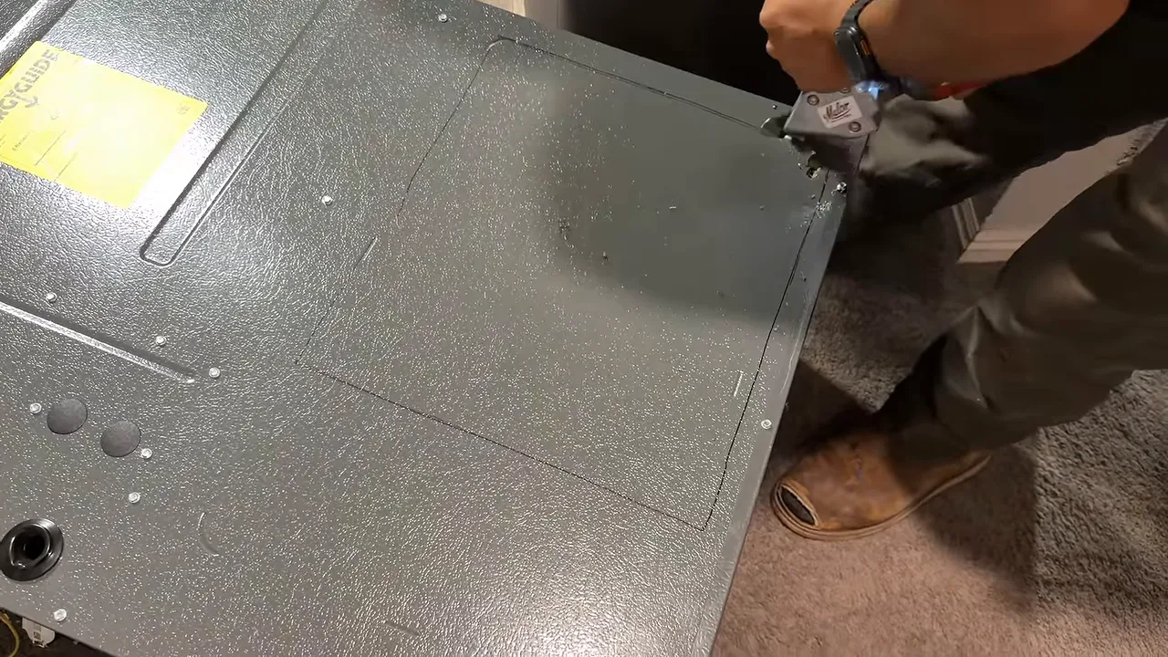
The narrower furnace required a small spacer at a return connection. We reinstalled the filter rack and filter, attached the return connections with sheet metal screws, and prepared the top of the furnace for the evaporator coil.
5. Set the Coil and Route the A2L Mitigation Wiring
Before bringing the evaporator coil into the mechanical room, we removed its front panel and routed the refrigerant mitigation sensor wiring through the designated opening. Doing that in an open area was easier than trying to fish it through after the coil was in place.
We applied the cabinet-joint sealant around the furnace-to-coil mating surface and set the coil in position. That joint needs to be properly sealed so supply air stays in the duct system.
One advantage of the matched equipment on this job was the integrated mitigation connection. The sensor wiring connected to the compatible furnace control board rather than requiring a separate improvised control arrangement.
Do not confuse a convenient plug connection with a complete safety check. Sensor placement, wiring, compatibility, and mitigation operation still need to meet the equipment instructions.
6. Build the Sheet Metal Transition Without Overcomplicating It
The new coil did not connect directly to the existing supply plenum, so we built a transition. This is one area where the right kit saves a bunch of time.
We used an HVACDirect transition kit that cost about $100 at the time of this job. It included sheet metal panels, S-cleat, a hand bending tool, self-drilling screws, a driver bit, and instructions. The panels measured approximately 16 by 26 inches, so checking the required transition dimensions before cutting was important.
Plan the seams before marking the panels
There are a couple of ways to handle the coil cabinet’s attachment edges. Where space allows, a folded panel edge may work. We were cutting it close on material dimensions, so we bent the cabinet attachment tabs upward and fastened the transition panels directly from the side.
For the transition itself, our approach was straightforward:
- Hold each panel in its actual installed position.
- Mark the corners where it meets the coil and existing plenum.
- Add the needed material allowance for the planned seams.
- Use S-cleat to receive the adjoining panel edges.
- Secure the panels and seal the completed joints.
On the back panel, we allowed an extra inch at each side for the folded edges and S-cleat connections. Some adjoining panels could remain flat because the receiving edges and cabinet tabs already provided the attachment points.
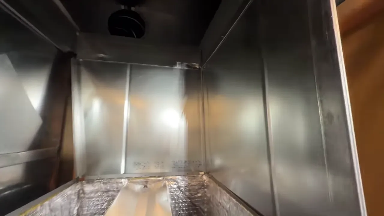
The remaining panel was marked in place, cut to fit with its seam allowance, slid into the receiving cleat, and secured with screws at the top and bottom. We then sealed the joints.
A bench shear made the straight cuts much quicker. Mine cost about $300 when I bought it, and I added locking casters so it could roll in and out of the trailer. A bar folder is handy for the bends. Neither tool replaces careful layout, but both save time if you do this work regularly.
7. Pressure-Test, Evacuate, and Verify the Hold
Once the refrigerant connections were complete, we pressure-tested the field piping and coil before releasing the outdoor unit’s factory charge.
On this job, the test pressure was approximately 344 psi, and the pressure remained steady over the roughly 10-minute check shown. That was our job-specific reading, not a recommended test pressure or duration for every system. Use the manufacturer’s specified dry-nitrogen test procedure and leak checks.
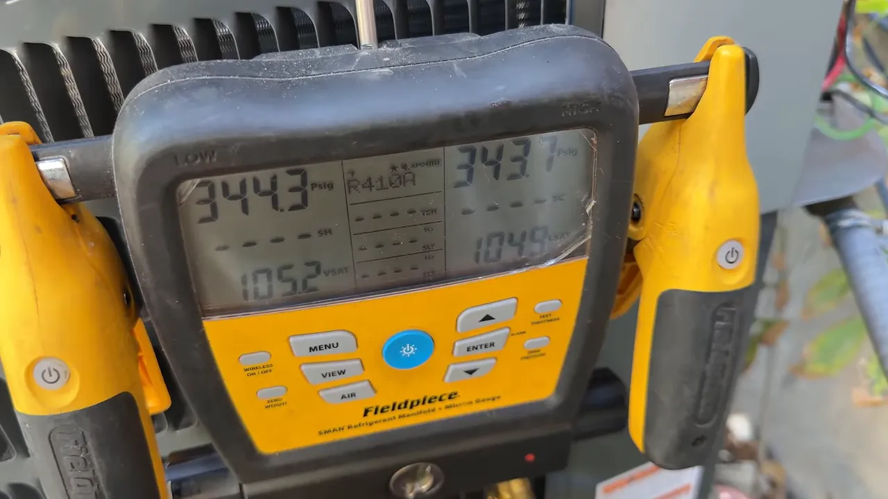
After testing, the nitrogen test gas was removed before evacuation. Releasing test gas is not the same as releasing refrigerant, and it needs to be done in a controlled, safe manner. A gas purge does not replace keeping the lines clean in the first place.
A simple vacuum setup has fewer potential leak points
We used a Fieldpiece vacuum pump, a large evacuation hose, a three-way Schrader core removal tool, and a separate micron gauge. Removing the valve core improves the evacuation path, while using fewer hoses and fittings reduces potential leak points compared with pulling through a conventional manifold.
The gauge initially indicated about 39 microns while the pump was running. However, it was close to the pump connection, so that low number alone did not establish the condition of the entire circuit.
The useful check was the isolated hold:
- We isolated the system from the vacuum pump.
- We stopped the pump and allowed the reading to rise and stabilize.
- Our check was to remain below 500 microns after five minutes.
- The final reported reading was approximately 110 microns after five minutes.
That was a strong result for this installation. For another system, follow its specified evacuation target, gauge placement, and decay-test requirements rather than copying only our five-minute threshold.
Release the factory charge only after testing passes
After the hold passed, we admitted refrigerant from the outdoor unit, removed the evacuation equipment using the core tool, reinstalled the Schrader core, and fully opened the service valves. The service valves on this Goodman were particularly tight, so using the proper tool mattered.
We also cleaned the oil residue left around the service connection before insulating the suction line. Finishing the piping cleanly makes later inspection easier.
8. Finish the Connections and Test Both Operating Modes
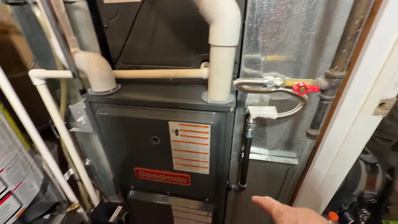
Inside, the finished installation included the new gas connection, electrical switch, venting, condensate piping, mitigation wiring, and insulated suction line. Both the furnace and coil condensate drains were routed to the condensate pump.
One detail deserves special care: the furnace exhaust connection. A removable connection can be helpful for future service, but silicone is not a universal substitute for solvent cement or a specified mechanical vent connection. Use exactly the connection and sealing method approved for the furnace and vent system. An unapproved exhaust joint can leak combustion gases.
With the indoor system calling for cooling, we restored outdoor power and started the condenser. It sounded good immediately, but startup is not the same as commissioning.
We let cooling run for about 15 to 20 minutes before checking the temperature difference between return and supply air, commonly called delta T. Our target on this job was roughly 17 to 20°F of cooling temperature drop, and the finished system delivered a 20°F delta T.
We then ran the gas heating cycle. We were looking for approximately 45 to 50°F of temperature rise on this installation, and heating operation checked out.
Those numbers belong in context. Cooling temperature split varies with airflow and indoor conditions, and furnace temperature rise must fall within the unit’s rated range. A good delta T does not, by itself, verify refrigerant charge, airflow, gas setup, or combustion safety. Complete the manufacturer’s startup checks rather than stopping at the vent temperatures.
The Finished Result: Careful Work Makes the Difference
We finished by rewrapping the deteriorated outdoor suction-line insulation and checking the completed installation. The new system was operating properly in cooling and heating, and the customer was happy with the result.
The replacement was expected to be quieter and more efficient than the troublesome older equipment. Goodman’s advertised 10-year warranty was another benefit discussed for the system, though the applicable coverage and registration requirements should always be verified for the equipment purchased.
A full HVAC replacement is not one mysterious task. It is a sequence of understandable jobs: document the connections, remove the equipment safely, fit the cabinets and ductwork, keep the piping clean, test thoroughly, and verify operation. The hands-on work becomes much more manageable when you approach it that way, while leaving regulated or specialized work to appropriately qualified people.
For ongoing filter maintenance, the installation sponsor, Filterbuy, offers bulk filters and custom sizes delivered to your door.
I sourced the replacement equipment and transition kit through HVACDirect. If you are comparing equipment for a replacement, my code DIYHVAC offers 5% off your order.
|


