Installing your own mini split can save a lot of labor, but mounting the equipment is only part of the job. Somebody still needs to pressure test the refrigerant circuit, pull a proper vacuum, verify that it holds, and make sure the system starts up correctly.
That is what I like about GWIN’s assisted DIY approach. You handle the installation work, and GWIN arranges for a local HVAC professional to finish the commissioning. You get the satisfaction and potential savings of doing the hands-on work without having to take on the entire refrigeration side yourself.
For this project, we installed a GWIN King 12,000 BTU single-zone mini split. The indoor installation was straightforward, the outdoor line routing came out clean, and the finished system delivered nice, cold air. Here is how the job came together, including the details that made it easier and the checks that mattered before startup.
What You'll Learn
- GWIN pairs homeowner installation work with professional pressure testing, evacuation, and startup.
- Planning the line route and maintaining downhill drainage prevent difficult installation problems.
- Smart Lock fittings eliminate field flaring but still require careful assembly and leak testing.
- Electrical specifications, test pressures, and refrigerant charge requirements must match the exact equipment.
Table of Contents
- What Makes GWIN’s Assisted DIY Approach Different?
- 1. Plan the Indoor Location, Outdoor Pad, and Line Route
- 2. Work Out the Electrical Supply Before Hanging the Head
- 3. Lay Out and Secure the Indoor Mounting Plate
- 4. Prepare the Indoor Head Before Putting It on the Wall
- 5. Drill the Wall Penetration With Drainage in Mind
- 6. Route the Line Set and Install the Cover Base
- 7. Make the Smart Lock Refrigerant Connections
- 8. Hand the System Over for Pressure Testing and Evacuation
- 9. Start It Up and Check the Finished Installation
- Why This Is a Smart Middle Ground for DIY HVAC
What Makes GWIN’s Assisted DIY Approach Different?
GWIN offers both mini split and ducted systems. The big advantage here is the division of labor: the homeowner installs the equipment, then a professional handles the final testing and startup.
For this mini split, that professional commissioning includes:
- Pressure testing the field-installed refrigerant circuit.
- Checking the connections for leaks.
- Evacuating the indoor coil and line set.
- Performing a vacuum decay test.
- Opening the refrigerant service valves and verifying operation.
GWIN also advertises a 10-year product warranty and a one-year bumper-to-bumper labor warranty. Confirm the current warranty terms and installation requirements for your purchase, but that professional finish and labor coverage are a big part of the appeal.
Keep the DIY boundary clear: this is an installation walkthrough, not a substitute for the equipment manual, permits, or local code. Electrical work should be completed by a qualified person where required, with power isolated and verified off. Leave commissioning and refrigerant work to the assigned professional. The EPA’s Section 608 technician certification guidance explains the certification requirements for covered refrigerant service work.
1. Plan the Indoor Location, Outdoor Pad, and Line Route
Our indoor head was going between two windows. Outside, the line set would travel down the wall, turn beneath the window trim, and continue down to the condenser.
Planning that whole route before drilling makes a difference. You need room for more than two copper tubes. The refrigerant lines, interconnecting cable, and condensate drain all need a workable path.
Before setting anything, identify:
- The indoor head location and required ceiling clearance.
- Stud locations and suitable mounting points.
- A clear wall penetration location.
- A continuously downhill route for the condensate drain.
- The outdoor unit location, required clearances, and service access.
- The electrical supply route and disconnect location.
- Any trim or siding details that require offsets in the line-set cover.
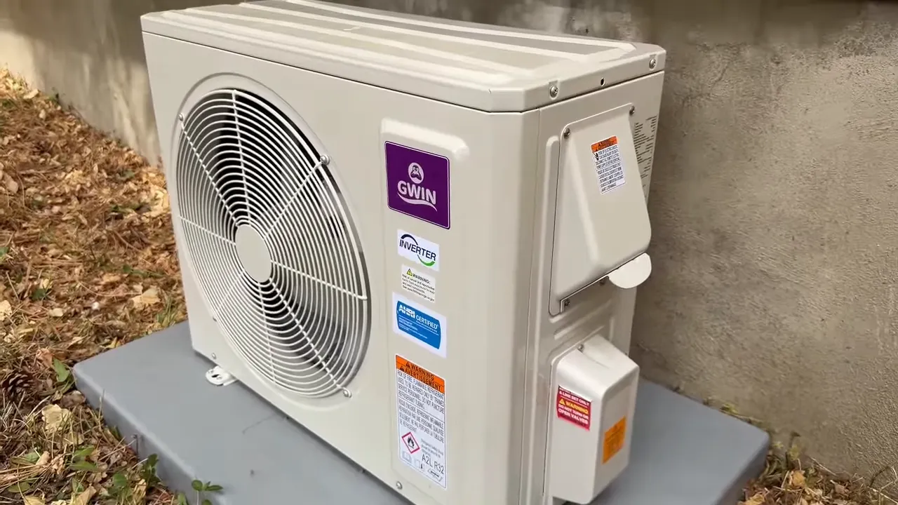
We cleared the ground to give the equipment pad a stable base, leveled the pad, and secured the condenser to it.
These homeowners intended to use the system for cooling, so we used a low pad installation. For winter operation, elevation deserves more attention. Follow the manufacturer’s requirements and account for local snow and drainage conditions rather than assuming a ground-level installation will work everywhere.
2. Work Out the Electrical Supply Before Hanging the Head
Electrical routing can be one of the trickier parts of a mini split installation. In this house, we had an unused 20-amp, two-pole, 240-volt breaker available in a nearby panel. That gave us a convenient route through the adjacent room and out to the condenser.
Those numbers describe this installation, not every 12,000 BTU mini split. Use the equipment nameplate and installation manual to determine voltage, conductor sizing, and allowable overcurrent protection. Do not select a circuit from cooling capacity alone.
Route and protect the conductors
Our route used roughly 20 feet of half-inch liquidtight conduit. To make the pull easier, we held the conduit as straight as possible, ran a fish tape through it, and made a smooth taped connection at the leading end of the wiring.
A smooth transition matters because a bulky taped joint can catch at the conduit entrance. Having one person feed while the other pulls also helps keep things moving without excessive force.
One important qualification: we used 10/2 cable during this job, but ordinary NM-B cable is not suitable for wet locations, including outdoor conduit interiors. A weather-resistant conduit does not make its interior a dry location. Have the electrical installer select conductors, cable types, fittings, and raceway sizing approved for the actual route.
Mount the disconnect and prepare the entries
We installed a 30-amp non-fused disconnect at an accessible height near the outdoor unit, then connected it to the condenser with a liquidtight whip.
The disconnect rating is not the same thing as the breaker rating. Its location, rating, and any fuse requirements must match the equipment instructions and applicable code. Do not treat a six-foot distance as a universal disconnect-location rule.
A small time-saver is to remove the needed knockouts before mounting the disconnect. The same idea applies to the condenser’s removable electrical cover: prepare the supply and interconnecting-cable entries while the cover is still supported by the unit, taking care not to damage anything behind it.
Identify the connections correctly
This 240-volt outdoor unit used two hot conductors and an equipment ground for its supply. Where a white conductor is legally used as a hot, it needs the required reidentification so it cannot be mistaken for a neutral.
Inside the disconnect, the incoming supply connects to the terminals marked line, and the outgoing condenser feed connects to load. Follow the labels rather than assuming terminal positions are the same on every disconnect.
Once the supply wiring was finished, we secured the route, sealed the exterior penetration, replaced the panel cover, and kept the condenser disconnected from power while completing the installation.
3. Lay Out and Secure the Indoor Mounting Plate
The kit included the indoor head, a mounting template, drain hose, remote and holder, insulation pieces, and refrigerant connection hardware. The line-set package also included a two-piece wall sleeve.
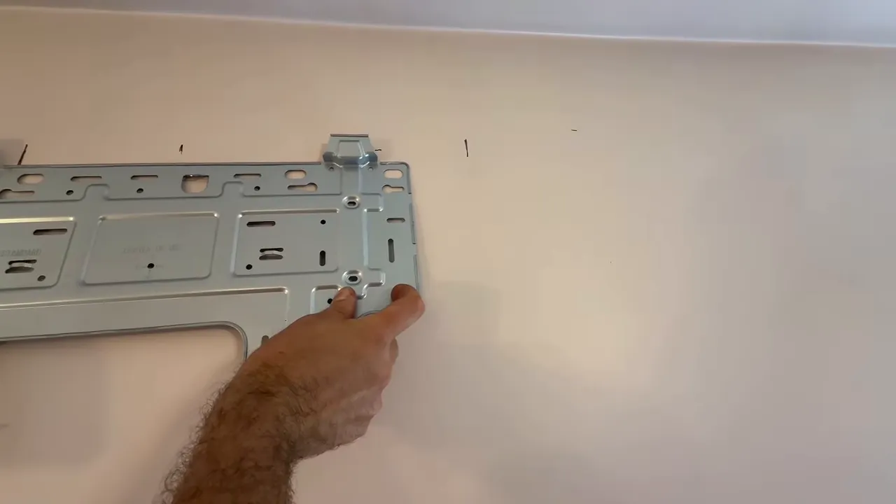
We removed the metal mounting plate from the back of the head and used the template to center the unit between the windows. For this installation, we planned approximately six inches of clearance below the ceiling for the return-air intake. Check the specified clearance for your exact model.
Next came the studs. I prefer to catch at least one stud, and two when the layout allows it. Here, the centered mounting position did not line up with both studs, so we used wood attachment where available and suitable wall anchors at the remaining locations.
The anchors used on this job were labeled for 70 pounds, but anchor ratings depend on the wall material and installation conditions. Use fastening methods appropriate for the unit, mounting plate, and wall construction.
4. Prepare the Indoor Head Before Putting It on the Wall
It is much easier to make the indoor electrical connections while the head is supported on its packaging than after it is hanging near the ceiling.
We carefully repositioned the refrigerant stubs for a rear exit, then fed the interconnecting cable through the opening into the terminal compartment. Bend the tubing gently and avoid putting stress on the connections.
The important wiring detail is matching terminal numbers between the indoor and outdoor units. Our cable had red, black, white, and green conductors. We recorded their positions at terminals 1, 2, 3, and ground, then matched those positions outside.
Do not assume wire color alone tells you where a conductor belongs. Follow the unit’s wiring diagram, secure the cable with its clamp, and replace the electrical cover before hanging the head.
5. Drill the Wall Penetration With Drainage in Mind
Our refrigerant lines, drain, and cable all exited through one opening on the right side of the mounting plate.
We first opened the drywall and inspected the wall cavity before drilling through the exterior. That let us confirm the route cleared the stud and check for obstructions.
The opening needs a slight downward slope toward the outside. The condensate drain must not climb as it leaves the indoor unit. An uphill section can hold water and lead to a leak inside the house.
Use the template to position the opening, and size the hole for the specified sleeve and bundle. This is worth checking before you get the hole saw out.
On this job, the hole saw available was too small for the supplied sleeve, so we sealed the penetration without that sleeve. For a planned installation, have the correct-size bit ready and follow the manufacturer’s sleeve and sealing requirements.
With everything prepared, we fed the cable through first, guided the tubing and drain outside, and hooked the head onto the mounting plate. Once it was seated, the remaining work moved outdoors.
6. Route the Line Set and Install the Cover Base
Outside, we gently directed the tubing downward and sealed around the wall penetration.
The indoor coil released its factory nitrogen holding charge when the shipping connection was opened. That is a useful indication that the coil arrived pressurized, but it does not replace the pressure test of the completed installation.
Before making the upper connections, we installed sections of the line-set cover base. This particular cover had movable clips that accepted zip ties. Those clips made it much easier to hold the tubing, cable, and drain in position instead of fighting the whole bundle while trying to snap on a lid.
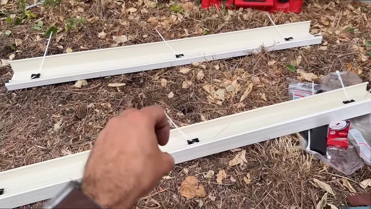
The route went down the wall, across beneath the window, and down to the condenser. A piece of trim projected about an inch and a half, so we had to jog the cover outward around it.
We also needed more drain hose than the roughly 10 feet supplied. Check the full drain route during planning so an extension does not become a last-minute surprise, and maintain the downhill slope through that extension.
7. Make the Smart Lock Refrigerant Connections
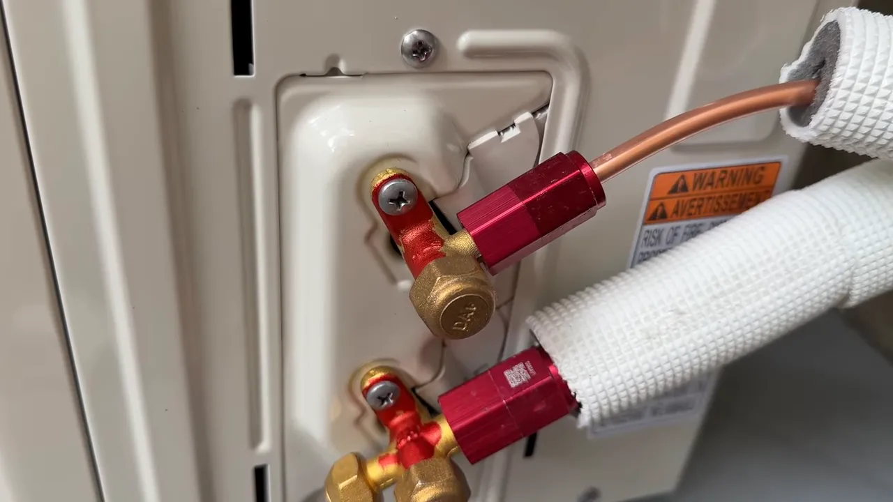
This GWIN kit used Smart Lock fittings rather than requiring us to flare the line-set ends. We used four fittings: two at the indoor-unit connections outside the wall and two at the condenser.
That removes the need for a flaring tool, but it does not eliminate the need for careful preparation or professional leak testing. We still needed a copper tubing cutter, marking tools, and wrenches.
Cut, clean, and mark the tubing
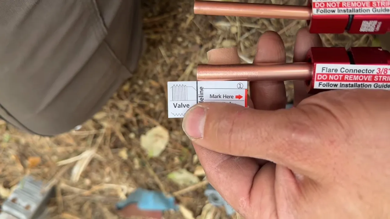
For this system, the refrigerant lines were 1/4 inch and 3/8 inch. Each fitting kit included a depth-marking guide, with the appropriate reference for the tube size.
- Route the tubing and establish the needed length without pulling it into position under tension.
- Cut the copper squarely and prepare it according to the fitting instructions, keeping debris out.
- Slide the required fitting components onto the tubing.
- Use the supplied guide to mark the correct insertion depth.
- Align the tubing straight with the mating connection.
The depth mark gives you a visible reference. If the tube moves while you assemble the fitting, that mark helps you catch it.
Seat the fitting and tighten it as specified
We held the tubing in alignment, brought the connection together, and hand-tightened the mating components in the sequence specified for the fitting. Before final tightening, we checked that the insertion mark still lined up correctly.
For the fittings used here, final wrench tightening closed the specified gap. A backup wrench prevented the assembly from twisting the tubing or stressing the equipment connection.
Use the instructions supplied with your exact fitting. These are not conventional flare nuts, and their assembly procedure should not be replaced with a generic flare-tightening method.
We repeated the process at the condenser after cutting both lines to their final lengths. With the electrical connections matched and the tubing connected, the system was ready for professional commissioning.
8. Hand the System Over for Pressure Testing and Evacuation
This is the handoff point in GWIN’s assisted DIY process. The local technician takes over to prove the installation is tight, remove air and moisture, and prepare the system for operation.
Because I am an HVAC contractor, I completed that work on this installation. The measurements below describe this job, not universal test settings for other equipment.
Nitrogen pressure test
We used an Appion 5/16-inch core-removal tool at the service connection and connected a regulated nitrogen supply and digital manifold.
The pressure was raised in stages. We began with a lower-pressure check for obvious leaks, then brought the field-installed circuit to approximately 400 PSI for the tightness test. The nitrogen regulator was set higher, around 500 PSI, but that was not the final circuit test pressure.
The technician must use the manufacturer’s specified test pressure and appropriately rated equipment. Never substitute oxygen or compressed air for a proper nitrogen test.
After allowing the pressure to stabilize, we monitored the pressure differential and checked the connections with leak-detection solution. Everything checked out, so we safely released the nitrogen before evacuation.
Pulling a vacuum
Our evacuation setup used a NAVAC vacuum pump, a large-diameter True Blue hose, the core-removal tool, and a CPS micron gauge. Removing the Schrader core helped reduce restriction.
We were looking for a deep vacuum, with 500 microns as the general target discussed for this job, followed by an isolation test. The equipment manufacturer’s evacuation and standing-vacuum requirements take priority.
This was a new, short line set, and the vacuum dropped quickly. We reached about 260 microns in less than two minutes, then continued pumping for roughly 10 minutes before isolating the system.
The vacuum decay test
A low reading while the pump runs is not the whole test. Once isolated from the pump, the system needs to hold an acceptable vacuum.
Our reading rose slightly after isolation, then stabilized around 86 to 88 microns. That was an excellent result for this installation.
With testing complete, we isolated the micron gauge, opened both service valves fully, reinstalled the valve core, and removed the service equipment.
This particular GWIN King was factory charged for a 25-foot line set, and our installed line set was exactly 25 feet, so no additional refrigerant was needed. Different models and line lengths can require different charge adjustments.
9. Start It Up and Check the Finished Installation
After restoring the covers and connecting power, we started the system in cooling mode.
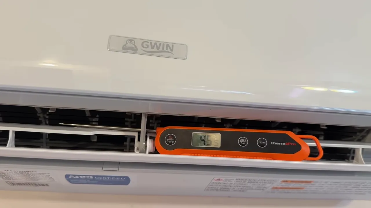
The room was approximately 77°F, and the discharge-air measurement was about 45.5°F. That is roughly a 31.5°F difference at that moment, and the unit was putting out nice, cold air.
That reading describes our startup conditions, not a temperature split every mini split should produce. Final commissioning should follow the manufacturer’s checks rather than relying on one air-temperature measurement.
The remote was straightforward, with mode selection, temperature adjustment, and fan settings. The indoor head looked clean between the windows, and the outdoor cover kept the line route tidy despite the offset around the trim.
Why This Is a Smart Middle Ground for DIY HVAC
The biggest benefit is not simply that the fittings are easier or that the mounting work takes relatively few tools. It is that you can handle a substantial part of the installation while leaving the critical testing and startup to somebody equipped to do it properly.
For this job, the details that paid off were planning the route first, preparing the indoor wiring before hanging the head, keeping the drain downhill, supporting the bundle before making connections, and checking every fitting’s insertion mark.
The finished installation came out great, and the homeowners were happy with the result. If you are comfortable with the mounting and routing work but want professional reassurance at startup, GWIN’s assisted DIY approach is worth considering.
|