Replacing an old HVAC system is not just a matter of swapping two boxes. The details that make the job turn out well are the coil preparation, the duct transition, the refrigerant connections, the drainage, and the testing before startup.
On this job, we replaced an aging Ducane outdoor condenser and an approximately 30-year-old Lennox furnace with a new Goodman system from HVACDirect. The new setup included a condenser described as 16 SEER, a 96% efficiency gas furnace, and an evaporator coil intended for R-32 refrigerant.
The installation went really smoothly. A little preparation ahead of time and a precut transition kit saved a lot of work. Here is how the project came together, including the measurements, tools, and checks that mattered along the way.
Safety first: This is an educational installation walkthrough, not a substitute for the equipment manuals, permits, or qualified help. Refrigerant work requires appropriate EPA Section 608 certification in the United States. Gas, electrical, venting, and A2L refrigerant work also carry serious hazards. Follow the manufacturer’s instructions and local requirements rather than copying job-specific measurements or methods. The EPA’s technician certification guidance explains the refrigerant certification requirements.
Table of Contents
- What You'll Learn
- Inspect and Prepare the Evaporator Coil Before Installation Day
- Plan the Removal Around What Can Stay
- Set the New Equipment and Check the Existing Electrical Circuit
- Fit the Furnace, Return Opening, and Coil
- Build the Supply Transition Without Starting From Flat Sheet Metal
- Fit and Join the Refrigerant Lines
- Pressure-Test the Connections Before Pulling a Vacuum
- Evacuate the Line Set and Verify the Vacuum Holds
- Reconnect the Gas Supply and Sediment Trap
- Release the Refrigerant Charge and Restore the Service Ports
- Finish the Venting, Condensate Drain, and Controls
- Start the System and Check the Results
- What Made This HVAC Replacement Go Smoothly
What You'll Learn
- Preparing the evaporator coil and sensor cable ahead of time reduces installation-day work.
- A precut transition kit simplifies fitting the new coil to existing supply ductwork.
- Nitrogen leak testing and an isolated vacuum hold provide separate checks before refrigerant release.
- Existing filters, wiring, and line sets require compatibility checks before reuse.
Inspect and Prepare the Evaporator Coil Before Installation Day
I like to get the small preparation tasks out of the way before the old system comes out. The evaporator coil is a good place to start.
Separate minor fin damage from actual tubing damage
The coil arrived protected with foam packaging, with the installation paperwork tucked inside. Be careful reaching into the cabinet. Those thin aluminum fins can cut your hand, and they bend easily.
A few small fin imperfections are not unusual on a new coil. What deserves closer attention is a deep gouge, crushed section, or damage that reaches the refrigerant tubing behind the fins.
One connection on this coil had also been pushed slightly out of position during shipping. With the front cover removed, we checked behind the insulation for kinks before gently correcting the alignment. A connection that looks bent is not automatically harmless. Inspect the tubing before trying to move anything.
Route the A2L sensor cable while the coil is accessible
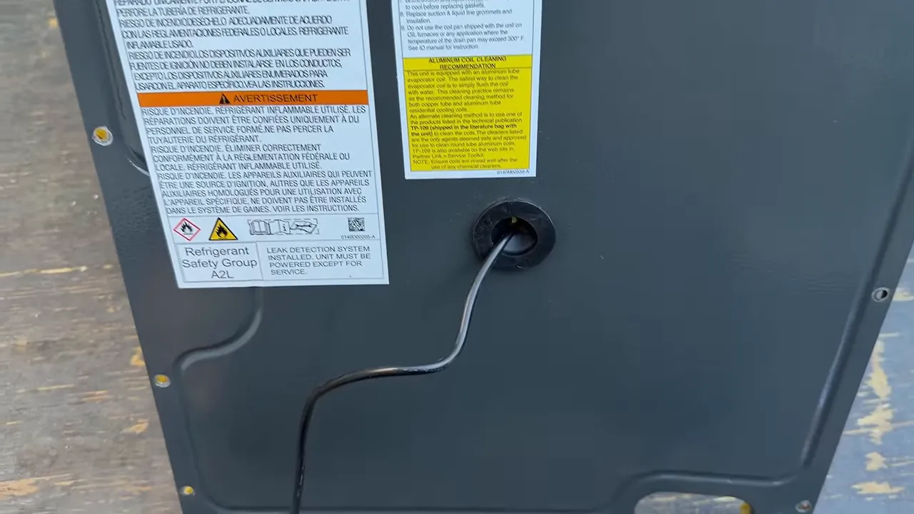
This coil had a sensor cable inside the cabinet that needed to come through the front panel. Doing that on a work surface was much easier than reopening the cabinet after installation.
For this particular cabinet, we removed the front-panel screws except the uppermost and lowermost pairs, then took off the front cover. The preparation involved:
- Removing the designated front-panel knockout.
- Installing the black protective grommet supplied in the installation packet.
- Releasing the cable from its shipping ties.
- Passing the four-pin connector through the grommet.
- Managing the slack while reinstalling the front panel.
- Making sure the condensate-opening grommet seated correctly.
We also installed the drain fittings ahead of time. That left fewer little tasks to deal with once the coil was sitting on the furnace.
The red-capped factory connection prompted another common question. The coil was shipped with a nitrogen holding charge, not its operating refrigerant charge. Its labeling and red identification relate to its intended A2L refrigerant application. There was no installation adjustment needed to the internal TXV or that factory charging connection.
Routing the cable is only preparation. The sensor and any associated mitigation controls still need to be connected and commissioned according to the matched system’s instructions.
Plan the Removal Around What Can Stay
The old furnace had an evaporator coil enclosed in sheet metal above it. Before cutting anything, we looked at the supply duct, PVC venting, gas connection, return connection, and filter rack.
The existing return already had a nice Honeywell 4-inch filter rack. Normally, that is something we would add during a replacement, so keeping this one made sense. We cleaned it up and planned to reconnect it to the new furnace.
The removal started with shutting off the furnace breaker and gas supply. Refrigerant had to be properly contained or recovered before disconnecting the refrigerant circuit.
A practical moving tip: if an old furnace needs to go up a flight of stairs, removing the blower assembly can reduce the weight considerably. It is one of the heavier parts of the cabinet.
Refrigerant containment is a separate, qualified task
The old condenser still had a functioning compressor, so we used a pump-down process to move refrigerant from the indoor coil and line set into the outdoor unit before removal.
The principle is simple: under suitable conditions, the compressor moves refrigerant into the condenser, where the service valves isolate it. Whether that procedure is appropriate depends on the equipment, its condition, and the manufacturer’s guidance. It is not a universal replacement for refrigerant recovery.
This work involves pressurized refrigerant and energized equipment. Do not manually force a contactor or run a compressor into a vacuum as a general DIY procedure. A qualified technician should select and carry out the appropriate containment or recovery method.
For terminology, the larger refrigerant tube is the suction line, also called the vapor line. On this type of installation, common sizes include 3/4 inch and 7/8 inch. The smaller tube on this job was the 3/8-inch liquid line. Those are job details, not a sizing rule for every system.
Preserve usable copper and protect open lines
After refrigerant handling was complete, we shut off outdoor power and checked before disconnecting the wiring. A noncontact tester can be a useful preliminary check, but it should not be the sole means of establishing that equipment is safe to work on. Disconnect placement and electrical requirements must follow the applicable code, not a simple distance rule.
We used a tubing cutter to disconnect the refrigerant lines, choosing cut locations that preserved enough copper for the new condenser. I also wanted to reroute the outdoor tubing so it followed the wall more neatly.
If a section is going to be reused, cleaning its exterior before cutting helps avoid doing that work with an open tube. Once cut, protect the openings promptly to keep dirt and moisture out.
With the electrical connections, refrigerant lines, return, venting, and gas connection safely disconnected, the old furnace and coil could come out.
Set the New Equipment and Check the Existing Electrical Circuit
Outside, we removed the old condenser pad because the replacement location already had a concrete base. The new unit was supported and leveled there. For another installation, support, anchoring, elevation, and clearances need to match the equipment instructions and site conditions.
The existing outdoor wiring and conduit were reusable on this job. The new condenser’s electrical information was checked against the circuit, and the existing 20-amp breaker was retained.
Do not confuse minimum circuit ampacity with a minimum breaker size. Conductor sizing and maximum overcurrent protection are separate checks. Read the actual equipment nameplate rather than assuming the old breaker and wire are suitable because they powered the previous condenser.
The outdoor control wiring was reconnected, and the electrical compartment was closed before moving on to the copper connections.
Fit the Furnace, Return Opening, and Coil
Cut the return opening before the furnace is boxed in
We measured and marked the new furnace’s side return opening, then made a starter opening so the sheet-metal shears could enter. A step bit is another way to start that cut.
The powered turbo shears made this much easier than cutting the entire opening by hand. Once the opening was finished, the existing filter rack could attach to the new cabinet.
Pay attention to condensate drainage
A 96% furnace produces condensate, so cabinet positioning and drain routing matter. For this installation, we checked the furnace front to back and side to side, then used a small piece of S-cleat as a shim to establish the intended drainage orientation.
The exact permissible pitch is model-specific. The important lesson is to check the installation manual and drain arrangement before fastening everything together. A cabinet that looks fine can still leave water sitting where it should not.
After positioning the furnace, we attached and sealed the return connection. We then applied sealant at the furnace-to-coil joint and set the evaporator coil in place, creating a sealed base for the supply transition.
Match filters by actual dimensions
The retained filter rack used a nominal 16-by-25-by-4-inch filter. That label alone is not enough to guarantee a replacement will fit.
Check the actual dimensions printed on the existing filter. Filters with the same nominal size can have different actual measurements. That matters whether you order through a supplier such as Filterbuy or buy locally.
Build the Supply Transition Without Starting From Flat Sheet Metal
The new furnace-and-coil stack did not line up directly with the existing supply duct. We needed a transition to bridge the gap.
Before building it, we measured the combined equipment height and the available space below the existing duct. The HVACDirect transition kit provided roughly 16 inches of starting height, so the panels needed trimming for this installation.
The kit cost about $110 at the time and included precut sheet-metal pieces, S-cleat, self-tapping screws, a driver bit, instructions, and a folding tool. Having those pieces ready saved a lot of fabrication time.
Fit the panels in place instead of guessing
- Cut the existing duct opening flush. An even edge makes the rest of the transition easier to fit.
- Install S-cleat at the receiving edges. The cleat provides a channel for the panel edges.
- Start with the back panel. It is easier to work from the least accessible side toward the front.
- Hold the panel in its installed position. Seat it against the coil and mark the actual fit.
- Add the required engagement allowance. Here, we added 1 inch at the edges that needed to slide into the S-cleat.
- Trim, fold, and repeat. Fit the remaining panels individually rather than assuming every side needs the same cut.
- Fasten and seal the assembly. The completed transition needs to be secure and airtight.
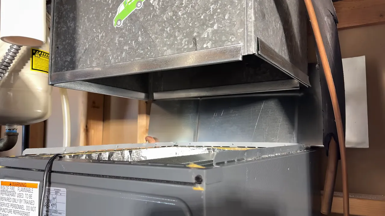
Not every edge needed the extra inch. At some corners, the S-cleat went directly onto the finished panel edge. Think through which edge inserts into a channel before making the cut.
We also used a 32-inch sheet-metal shear that cost around $200 at the time. For someone doing this professionally, straight cuts with less strain on the hands and forearms can make that tool worthwhile. The precut kit and powered shears were the biggest time savers on the ductwork.
Fit and Join the Refrigerant Lines
Outside, we dry-fitted copper elbows, street elbows, and couplings to get the routing where we wanted it. Assortment kits in the appropriate tubing sizes made it easy to piece the connections together.
For this job, I used Stay-Brite 8 solder with Stay-Clean flux. I have used that combination on many installations, and I like how manageable it is with properly fitted joints.
That preference is not blanket approval for every system. Confirm that the equipment manufacturer permits the joining method, especially on an R-32/A2L system. If brazing is required, follow its nitrogen-purge and heat-protection instructions.
Clean copper and close-fitting joints make the difference
The preparation was straightforward:
- Clean the mating copper surfaces with emery cloth.
- Apply a small amount of the appropriate flux.
- Avoid leaving excess flux at the tube opening.
- Assemble the fitting with a slight twisting motion.
- Wipe off excess flux before heating.
One trick I like is to make an awkward joint in a more comfortable position before installing the assembly. We removed one fitted section and soldered that joint horizontally, which was easier than working upside down beside the condenser.
Close-fitting manufactured fittings are especially helpful with this solder. A loose, oversized swaged connection leaves a larger gap, and Stay-Brite 8 does not handle that as well.
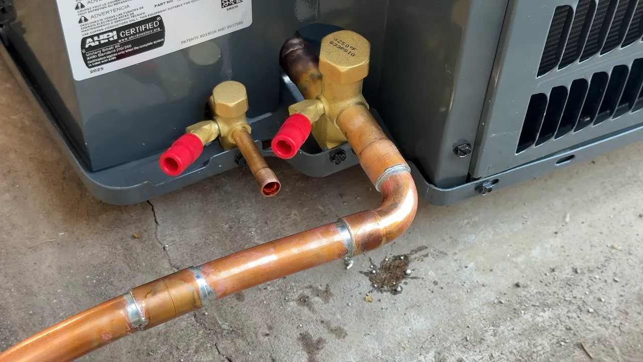
I mentioned its advertised 10,000-psi tensile strength during the job. That is a material-strength figure, not a refrigerant system working-pressure rating or a substitute for manufacturer approval.
Once the outdoor joints were finished, we insulated the suction line and moved inside.
Adapt the coil connections only within approved line sizing
The indoor coil still had its nitrogen holding charge. Releasing that charge in a controlled way before opening the connections gave us another indication that the coil had retained pressure during shipping.
The coil’s suction connection was 7/8 inch, while the existing suction line and new condenser connection were 3/4 inch. We used a reducer at the coil.
A reducer solves a connection-size mismatch, but it does not establish that a line size is suitable. The approved size still depends on the matched equipment, line length, and installation requirements.
Cutting a capped connection can also leave the opening slightly restricted. We needed to restore the opening so the mating tubing would fit, while keeping copper debris out of the circuit.
After completing the indoor joints, we refitted the cabinet grommets. This condenser had a factory-installed filter-drier, so we did not add a separate one at the indoor coil. Verify that detail for the exact model rather than assuming it applies to every Goodman or Amana unit.
Pressure-Test the Connections Before Pulling a Vacuum
Good-looking joints are not enough. The next step was a dry-nitrogen pressure test.
We used a Fieldpiece three-way core-removal tool at the suction service port. Removing the Schrader core opened up the flow path, and the tool also provided a convenient connection and isolation arrangement for the later vacuum test. An Appion core tool is another option.
The nitrogen cylinder connected through a regulator and manifold. On this installation, the test pressure was about 350 psig, with the gauge settling near 352 psig. That number belongs to this job. Always use the pressure and procedure allowed by the equipment manufacturer and the lowest-rated component.
I normally like to start at about 50 psig to catch a large leak before increasing to the full test pressure. Once pressurized, give the reading time to stabilize and check the joints with leak-detection bubbles.
We initially planned a short stabilization check, but the system remained under test for about 30 minutes while other work continued. The pressure rose slightly as conditions warmed, and the bubble checks showed no leaks.
Pressure changes need context. Temperature affects the reading, so a small movement on the gauge does not tell the whole story. The pressure hold and direct joint checks work together.
Plan your nitrogen supply ahead of time
Getting nitrogen can be a sticking point for a homeowner planning this work. I used a small cylinder purchased online and had a local Airgas location fill it.
At the time, the cylinder cost less than $100 and the fill was around $30. Rental or exchange may also be available. Check with the local supplier before buying a cylinder because acceptance, turnaround times, and prices vary.
After testing, the nitrogen must be released safely before evacuation. It is a high-pressure gas and an asphyxiation hazard, so use controlled depressurization and adequate ventilation. Releasing nitrogen does not replace evacuation or proper contamination control.
Evacuate the Line Set and Verify the Vacuum Holds
With the pressure test complete and nitrogen removed, we connected a NAVAC 3-CFM vacuum pump using a single large-diameter True Blue vacuum hose. The pump had a 1/2-inch port, and the service-tool end of the hose used a 1/4-inch connection.
A CPS micron gauge measured the vacuum. A regular manifold pressure reading cannot provide the same evacuation measurement.
My acceptance target for this job was to isolate the pump and keep the system below 500 microns for at least five minutes.
- Evacuation began: approximately 11:46 a.m.
- Isolation reading: approximately 150 microns at 12:14 p.m.
- Reading after the hold: approximately 160 microns.
That was a very small rise, and it stayed comfortably below the target.
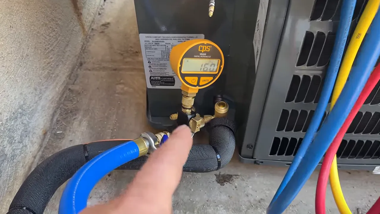
The initial estimate was 10 to 15 minutes, but the actual pump run was closer to 28 minutes. That is a useful reminder: finish based on the measured result, not the clock.
Gauge placement also matters. A gauge near the pump can read lower while evacuation is underway. In this setup, the isolation arrangement left the gauge connected to the system for the hold test. Whatever tools you use, make sure the test measures the system rather than an isolated hose or tool cavity.
Reconnect the Gas Supply and Sediment Trap
While the vacuum pump ran, we worked on the furnace gas connection. The cabinet had interchangeable side grommets, so we moved the gas-entry grommet to the left side to suit the existing supply.
We installed a sediment trap with a capped lower leg. Its purpose is to provide a collection point for debris rather than allowing a direct path into the gas valve.
For the threaded connections, I demonstrated both pipe-joint compound and gas-rated thread tape.
- Use a sealant approved for the gas service and connection. Ordinary tape is not automatically suitable.
- Apply a controlled amount. More compound mostly creates more mess and increases the chance of material entering the pipe.
- Keep sealant off the open end. Tape and compound belong on the appropriate threads, not across the bore.
- Wrap tape in the tightening direction. Looking directly at the end of a standard right-hand male thread, that is clockwise.
- Follow the tape label. The product used specified at least three wraps; I applied about five.
- Support the gas valve while tightening. Do not transfer pipe-wrench torque into the valve body.
Those are assembly details, not permission to skip gas testing. All disturbed gas connections need the required leak checks, and furnace startup must follow the manufacturer’s procedure.
Release the Refrigerant Charge and Restore the Service Ports
After the vacuum hold passed, we isolated the micron gauge from refrigerant pressure before opening the condenser’s service valves.
The factory charge was admitted into the evacuated indoor coil and line set in a controlled way, then both service valves were fully opened. We removed the vacuum hose and gauge and used the core-removal tool to reinstall the Schrader core under pressure.
The rotating magnetic holder on the Fieldpiece tool made the core easier to handle. Once it seated, it only needed to be snug, not forced tight. We checked that it sealed and reinstalled the service caps.
This installation had a very short line set, roughly 15 feet or less, with the condenser almost directly opposite the indoor equipment. I relied on the factory charge for this job rather than adding refrigerant.
A short line set alone is not proof of a correct charge. Check the manufacturer’s included line-length allowance and commissioning instructions. Longer runs may require additional refrigerant, and final charge verification should follow the specified method and operating conditions.
Finish the Venting, Condensate Drain, and Controls
Understand the furnace’s vent adapters
On this Goodman furnace, the exhaust pipe fitted into a cabinet connection. Service access matters here, but so does using the exact sealing method required by the furnace instructions. Do not assume silicone or a removable joint is acceptable wherever PVC venting connects.
The intake adapter had a handy feature: reversing the fitting allowed it to act as a coupling and accept the pipe directly. That avoided an additional fitting in this arrangement.
Combustion-air intake and exhaust connections have different requirements. Complete both according to the model-specific instructions rather than treating every joint the same way.
Use the supplied condensate components
The furnace included a condensate-drain kit that could be configured to either side. We installed it on the left to tie into the existing drain arrangement, cut the supplied tubing to length, and connected it.
Goodman made that portion pretty straightforward. Even so, the completed drain still needs the specified trap arrangement, slope, and any locally required provisions.
We finished the thermostat wiring, installed the new thermostat, sealed the transition seams with foil tape, and put the access panels back on.
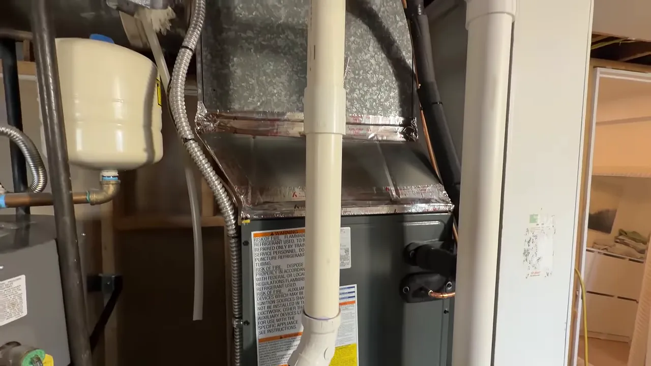
Start the System and Check the Results
With the installation assembled, we restored power and tested heating and cooling.
In heating, we checked operation and observed blue burner flames. Outside, the new condenser started quietly, and the discharge air felt warm as it rejected heat.
The final cooling check showed about 75°F indoors and 55°F supply air, a roughly 20°F temperature difference. The air felt great, and the installation turned out clean.
Those are encouraging operating observations, not a complete commissioning report. A hand over the condenser fan, blue flames, and a temperature split do not replace the manufacturer’s required electrical, airflow, gas, combustion, and refrigerant checks.
What Made This HVAC Replacement Go Smoothly
The biggest wins were not complicated. Preparing the sensor cable before installation saved reopening the coil. Keeping a suitable 4-inch filter rack avoided unnecessary replacement work. Fitting the copper before heating made the connections easier to manage.
The transition kit was especially useful. Being able to hold up a precut panel, mark the actual opening, trim it, and slide it into S-cleat was much faster than fabricating the whole transition from scratch.
Most importantly, we did not stop at getting the equipment connected. The nitrogen pressure test, bubble checks, evacuation, and isolated vacuum hold gave us measurable results before startup.
If you are comparing replacement equipment, HVACDirect supplied the Goodman system and transition kit used here. My code DIYHVAC offers 5% off through the linked offer.


