When the power goes out, getting electricity to a furnace can be more complicated than getting it to a refrigerator. A hardwired furnace does not have a plug you can move to a backup power source.
The idea behind this project is straightforward: replace the existing furnace service switch with a switch and receptacle combination, then supply the furnace through a grounded appliance cord. With an approved installation, switching to emergency power becomes a matter of unplugging the furnace rather than opening up its wiring every time.
That is the preparation I wanted for this furnace. But there is an important distinction: a convenient connection is only useful if the furnace manufacturer and local electrical requirements permit it. This is not a universal modification for every heating system.
Key Takeaways
- A permitted cord connection can simplify moving a furnace from normal power to a compatible backup source.
- Manufacturer instructions and local electrical requirements determine whether this furnace modification is allowed.
- The installation must preserve grounding, secure the cord, and account for any condensate pump supply.
- Test the complete backup arrangement before an outage rather than relying on the new connection alone.
Table of Contents
- Understand the Setup Before Changing Anything
- Parts Used for This Furnace Connection
- 1. Turn Off the Breaker and Verify the Power Is Off
- 2. Identify the Incoming Supply and Furnace Wiring
- 3. Configure the Combination Device as a Switched Receptacle
- 4. Install and Secure the Furnace Pigtail
- 5. Reconnect Hot, Neutral, and Ground
- 6. Inspect the Installation and Test Normal Operation
- Using the Furnace Connection During a Power Outage
- Prepare Before You Need Emergency Heat
Understand the Setup Before Changing Anything
Normally, the incoming electrical supply passes through the furnace service switch and continues into the furnace. In the arrangement shown here, the incoming supply instead feeds a switched receptacle. A short grounded cord, often called a pigtail, supplies the furnace from that receptacle.
The intended operation is:
- During normal use: The furnace cord plugs into the nearby switched receptacle.
- For local shutdown: The switch turns off power to that receptacle.
- During an outage: The furnace cord is unplugged from the normal supply and connected to a suitable backup source.
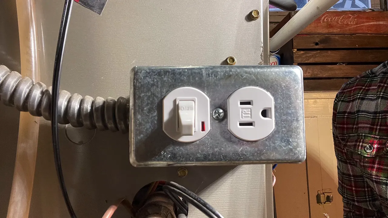
This project changes the electrical connection, not the furnace’s heating capacity or fuel supply. It also does not establish that a particular generator, inverter, or battery can operate your equipment.
Before proceeding, have a qualified electrician confirm whether a cord-connected installation is permitted for your furnace. Many furnaces require permanent wiring. Equipment instructions, grounding, disconnect requirements, circuit protection, and local code all matter. If this conversion is not permitted, ask about an approved transfer arrangement instead.
Parts Used for This Furnace Connection
The main components in this installation were:
- A combination switch and receptacle with a pilot light.
- A grounded appliance pigtail, supplied as a 6-foot cord and shortened for the installation.
- A 1/2-inch cable connector to secure the cord where it enters the enclosure.
- Lever-style wire connectors for the hot, neutral, and grounding connections.
- A short jumper conductor for the selected switch/receptacle configuration.
- Screwdrivers, wire strippers, and appropriate electrical test equipment.
Those are the components used here, not a sizing specification for every furnace. The cord, connector, switch, receptacle, jumper, and splicing connectors all need to be suitable for the equipment and installation. A connector’s nominal trade size alone does not establish that it is listed for a particular flexible cord.
1. Turn Off the Breaker and Verify the Power Is Off
The first job is at the electrical panel. Locate the breaker labeled for the furnace and turn it off. Do not rely only on the service switch beside the furnace.
Also, do not assume the panel label is correct. Once the switch cover is removed, the wiring needs to be tested before anything is disconnected or touched.
I used a noncontact voltage tester as an initial check. However, a silent noncontact tester is not proof that conductors are de-energized. A qualified person should verify absence of voltage with appropriate test equipment, checking the tester on a known live source before and after testing.
Keep the breaker from being turned back on while work is underway. Any backup supply must also remain disconnected. This is line-voltage wiring, so uncertainty about a conductor or test result is a reason to stop.
2. Identify the Incoming Supply and Furnace Wiring
With the circuit verified off, the existing switch can be removed from its box. On this furnace, the switch had an incoming power conductor and an outgoing conductor supplying the furnace.
It is important to distinguish those two sides:
- Line: Power arriving from the electrical panel.
- Load: Power leaving the switch toward the furnace.
The replacement receptacle also needs a neutral. In this installation, the incoming neutral continued through the switch-box area into the furnace, so it had to be disconnected inside the furnace and brought back into the exterior box.
That involved opening the furnace compartment, identifying the existing line-voltage connections, and separating the appropriate supply conductors. The incoming hot and neutral were then available at the switch box.
Take clear photographs and label connections before separating them. Your furnace may have different accessories, conductor colors, or connection points. The goal is to positively identify the existing circuit, not to assume another furnace matches this one.
3. Configure the Combination Device as a Switched Receptacle
A combination switch and receptacle can often be wired more than one way. For this project, I wanted the switch to control the receptacle so the local furnace shutdown function remained available during normal operation.
The device used here had a removable connecting tab. Its instructions showed a configuration with:
- The specified break-off tab removed.
- The incoming hot connected to the designated switch supply terminal.
- The incoming neutral connected to the designated receptacle neutral terminal.
- A jumper connecting the switch output to the receptacle’s hot connection.
- The equipment grounding conductor connected to the grounding terminal.
In that configuration, the receptacle is controlled by the switch, and the pilot light illuminates when the switch is on.
Use the wiring diagram supplied with the exact device. Do not identify terminals by descriptions such as top, bottom, or closest to the switch. Device orientation and internal connections vary, and pilot-light models can have additional wiring requirements.
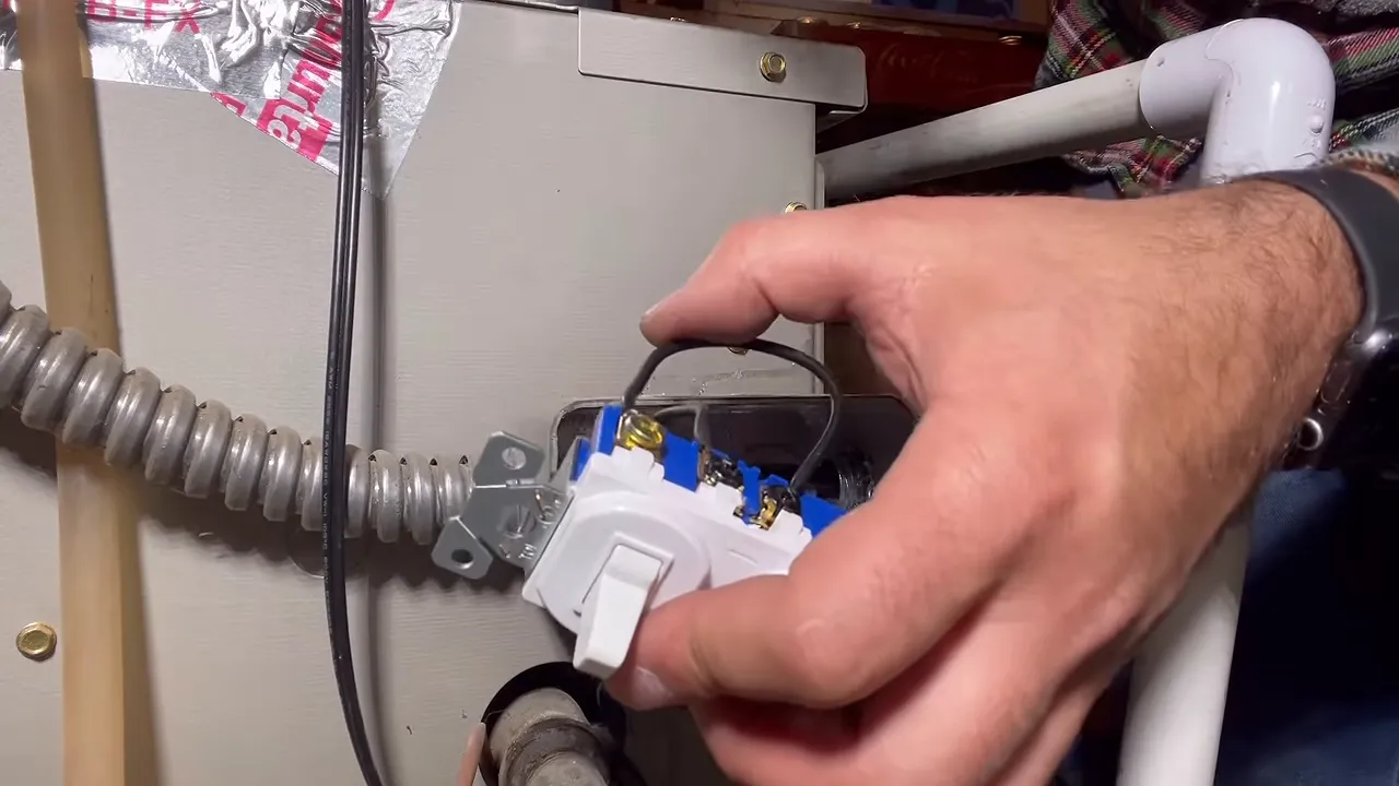
On this unit, the specified tab was removed by bending it back and forth with a tool. That work must not damage the device body or terminal support. Replace a damaged device rather than assuming it will be fine.
After making the connections to the manufacturer’s requirements, the conductors can be arranged inside the box and the device secured. The metal box and other required metal parts must remain properly bonded.
4. Install and Secure the Furnace Pigtail
The next part is the cord that will become the furnace’s electrical supply. Its plug stays outside the enclosure, while its hot, neutral, and grounding conductors connect to the furnace wiring inside the approved wiring space.
This installation used a 1/2-inch connector at the enclosure opening. Its purpose was to secure the cord and keep it from rubbing against a raw metal edge.
The useful sequence is to install the appropriate cord connector before fastening everything back together. That saves removing the switch a second time just to reach the connector.
The cord was fed through and adjusted to leave enough outside length to reach the receptacle with a little slack. You do not want a tight cord pulling against the plug or the internal connections, and you do not need a large loose loop hanging beside the furnace.
Keep the cord unplugged while preparing and connecting its conductors. Use the proper strain relief for the cord, with the outer jacket secured as its instructions require. Route the cord away from sharp edges, hot surfaces, moving parts, and access panels.
5. Reconnect Hot, Neutral, and Ground
Once the cord was secured, its internal end was shortened and prepared for connection. The three supply functions on the cord used here were:
- Black: The hot conductor supplying nominal 120-volt power.
- White: The neutral conductor.
- Green: The equipment grounding conductor.
Inside this furnace, there were also existing furnace supply leads and a three-conductor cable associated with a condensate pump. Those connections needed to be accounted for rather than left behind during the conversion.
Include the Condensate Pump When Applicable
Not every installation has a condensate pump. This one did, with blue identified as its neutral and brown identified as its hot conductor. Those identifications applied to this particular wiring arrangement.
The connection groups were organized by function:
- Neutral group: Cord neutral, furnace neutral, and the identified pump neutral.
- Hot group: Cord hot, furnace hot, and the identified pump hot.
- Grounding group: Cord ground, the furnace cabinet grounding connection, and other required equipment grounds.
Verify those functions against the equipment wiring diagrams. Do not use the blue and brown colors here as a general rule for other furnaces or pumps. Any existing condensate safety wiring must also remain intact.
Using Lever Connectors
I used Wago-style lever connectors for these splices. They make it easy to open a connection, insert a conductor, and close the lever to secure it.
The basic process is to:
- Select a connector listed for the conductor sizes and types involved.
- Strip each conductor to the connector’s specified length.
- Lift the lever and insert the conductor fully.
- Check its position through the clear housing where visible.
- Close the lever and gently check that the conductor is secure.
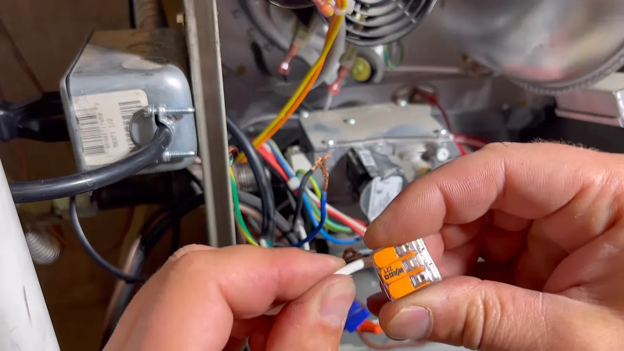
These connectors come in different port counts, so use one with enough approved positions for the splice. Do not put multiple conductors into a port unless that connector specifically permits it.
The finished wiring had three distinct connection groups: neutral, hot, and ground. The furnace cabinet remained connected to the equipment grounding path. Grounding and neutral serve different purposes and are not interchangeable.
6. Inspect the Installation and Test Normal Operation
Before restoring power, inspect the complete installation. This is the time to catch an unsecured cord, an incomplete splice, or a conductor that could be pinched by a cover.
- Confirm all terminations are secure and made to the applicable instructions.
- Check that no unintended bare conductor is exposed.
- Verify grounding and bonding connections.
- Check cord restraint and routing.
- Secure the device cover and required wiring enclosures.
- Restore the furnace panels required for normal operation.
For the normal-supply check, leave the local switch off, restore the furnace breaker, and verify the switched receptacle operates correctly. On this device, the small red pilot light illuminated with the switch on.
The light is a convenient indication, not a substitute for verifying correct receptacle wiring and grounding. After inspection and testing, the furnace cord can be plugged into its normal receptacle and the thermostat raised to call for heat.
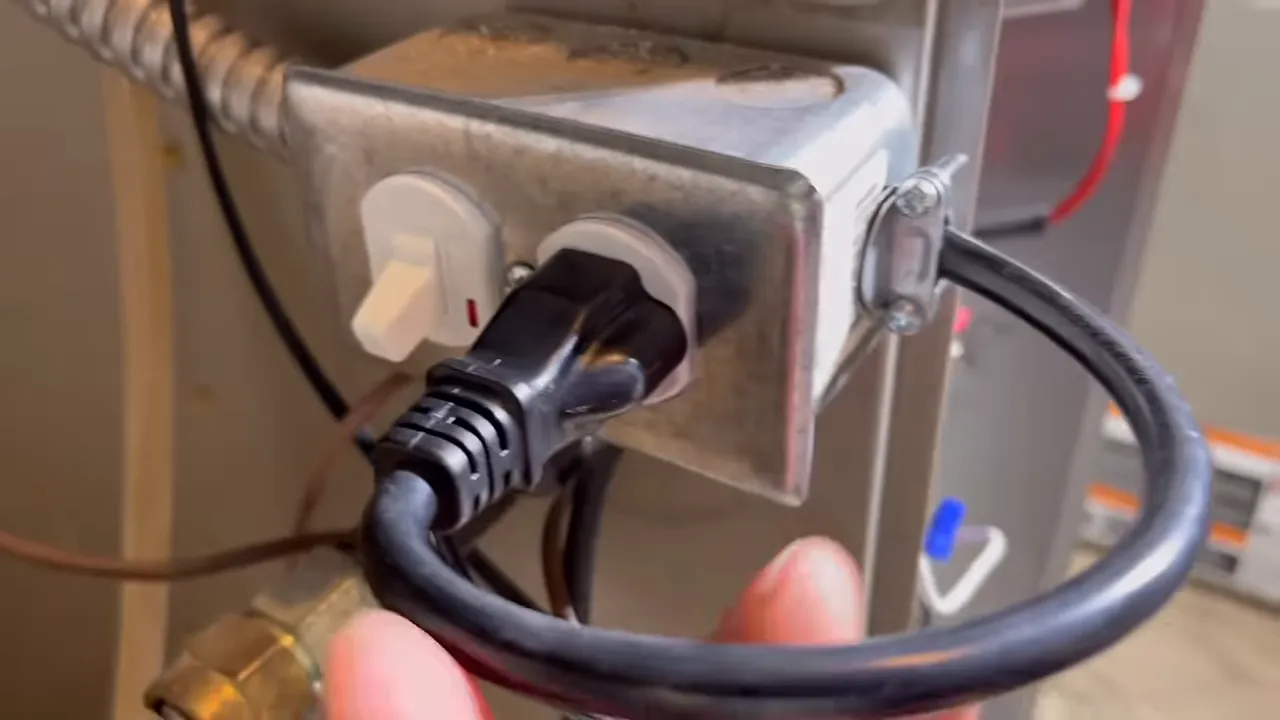
The furnace in this installation started and operated from the new cord connection. That is the intended result: normal furnace operation, with an accessible way to disconnect its electrical supply.
Using the Furnace Connection During a Power Outage
The practical benefit comes when utility power is unavailable. With an approved, tested installation, the furnace cord can be disconnected from the normal receptacle and connected to a compatible backup source without reopening the furnace wiring.
That source could be a suitable generator or a battery-powered inverter. I have also demonstrated supplying a furnace from a vehicle-connected inverter. The important word is suitable: this connection project does not determine the power source’s capacity or compatibility.
Before an emergency, confirm that the backup setup can handle the furnace’s starting and running requirements, plus any necessary condensate pump. Follow the furnace and power-source instructions for waveform, grounding, and neutral requirements. Available operating time depends on the energy or fuel supply, not merely on having a plug.
There is another important difference during backup operation: the switch on the normal receptacle no longer controls the furnace once its cord is plugged into a separate source. The backup source and its disconnecting arrangement must be handled accordingly.
Never feed generator or inverter power into a household receptacle, and never use a male-to-male cord. This arrangement is intended to disconnect the furnace from the normal supply before connecting it to backup power.
Generators and running vehicles also create carbon monoxide hazards. Keep them outdoors and away from building openings. For generator placement and other emergency precautions, review Ready.gov’s power outage guidance.
Prepare Before You Need Emergency Heat
The biggest advantage here is preparation. An outage is not the time to start identifying furnace wires, shopping for connectors, or discovering that your backup source cannot start the equipment.
If this connection method is approved for your furnace, get it installed, inspected, and tested ahead of time. If it is not, have an electrician provide an approved alternative. Either way, the goal is the same: a dependable plan for emergency furnace power without improvised wiring in the cold.
I keep the tools and connectors I use in my tool collection so you can research what your particular project requires.
|